Tiếng Việt
 日本語
日本語 한국어
한국어
Using Simcenter for Thermal Management of Electric Vehicles
Extending 1D system-level models with 3D ROM models
The battle between traditional Internal Combustion Engine (ICE) vehicles and electric vehicles will be a memorable one, driven by the high level of technological disruption within the automotive community and the rapid rise of electric vehicle manufacturers. While customers often focus on performance comparisons between ICE and electric vehicles, the key factors extend beyond top speed and acceleration. Range, efficiency, durability, and driving characteristics are typically of primary concern.
To ensure the market success of an electric vehicle, it is essential to reduce delays and improve productivity across different engineering teams (such as mechanical, thermal, electrical, controls, and software). Reduced Order Models (ROMs) derived from 3D CFD tools can replace 1D system simulation models to deliver more accurate and detailed results. As a result, teams can make better-informed and more confident design decisions.
A Reduced Order Model (ROM) is a simplification of a high-fidelity steady-state or transient model that preserves essential states and dominant effects, with the goal of reducing computational time or storage requirements for more complex models.
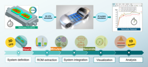
Typical steps for the BCI-ROM (Boundary Condition Independent Reduced Order Model) workflow are illustrated below, highlighting how users can directly benefit from high-fidelity 3D CFD models from Simcenter FLOEFD and integrate them into larger-scale 1D system simulation models in Simcenter Amesim.
Typical steps for the BCI-ROM workflow (Boundary Condition Independent Reduced Order Model)
Result accuracy is maintained while CPU performance is significantly accelerated, enabling longer and faster driving cycle simulations.
Power electronics cooling
Even though Porsche previously used air-cooling systems for their ICE vehicles, these are not ideal solutions for modern traction inverters due to high power density. As a result, it is not uncommon for automotive inverters to be liquid-cooled.
The PCB (Printed Circuit Board) assembly can be mounted on a cold plate, which facilitates thermal management of high-power components. The cold plate contains channels for fluid flow, with mass flow rate and fluid temperature controlled via a pump and a fan-cooled radiator.
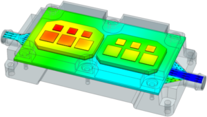
PCB cold plate model in Simcenter FLOEFD
1D system simulation
Simcenter Amesim is an integrated and scalable system simulation platform that allows system simulation engineers to evaluate and optimize the performance of mechatronic systems. It is used for the complete electric vehicle, except for the PCB cold plate. The first group includes the longitudinal vehicle, Vehicle Control Unit (VCU), and driver models, enabling the definition of basic parameters such as vehicle mass (dependent on battery pack mass), rolling resistance, aerodynamics, wheel size, gear ratios, and driving cycles (SFTP-US06).
The power electronics group includes a Permanent Magnet Synchronous Machine (PMSM), a medium-frequency three-phase inverter (allowing switching effects to be modeled at a faster intensity order), high- and low-voltage batteries, sensors, and controllers. Pumps, radiators, fans, expansion tanks, and sensors form the thermal management system.
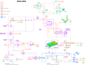
Simcenter Amesim electric vehicle model
Simcenter Amesim is perfectly suited for creating and validating system-level models. However, to support 1D system simulation calculations, reusing 3D models can sometimes be more appropriate for electronics and thermal management when certain 3D considerations are involved, which are difficult to capture with a purely 1D approach. A relevant example is a three-phase inverter. To analyze its performance, the temperatures of the IGBTs and diodes must be monitored to prevent overheating and to enable appropriate thermal derating.
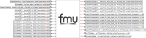
BCI-ROM of an inverter from Simcenter FLOEFD imported into Simcenter Amesim as an FMU
3D assembly modeling
Simcenter FLOEFD is a CAD-embedded solution that enables multiphysics simulations at early design stages, allowing engineers to eliminate undesirable design options. It is well suited for performing full 3D CFD simulations of a traction inverter to compute temperature distribution within the device, as well as flow modeling. However, due to the high complexity of the model and computational requirements, it is not feasible to run 3D CFD and 1D system models simultaneously.
To overcome this limitation, Simcenter FLOEFD allows you to extract Reduced Order Models (ROMs) that enable fast model execution (up to 40,000 times faster than traditional 3D CFD models). Such models are also boundary-condition independent, allowing you to change the thermal environment of the model (i.e., external heat transfer coefficients) without affecting solution accuracy. BCI-ROMs can be exported as Functional Mock-up Units (FMUs), which are portable and easily embedded into other tools.
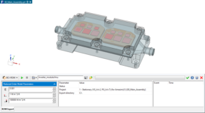
BCI-ROM export in Simcenter FLOEFD
1D–3D CAE: Combining system and assembly models
Simcenter Amesim is one of more than 100 tools that support FMU import and export. When the inverter FMU is imported into Simcenter Amesim, the system can be simulated. During simulation, the thermal loop provides transient HTC values and fluid temperatures to the FMU, while the heat flux of the cold plate and the temperatures of components and the cold plate are sent back to the system.
Since the thermal management system is a critical part of an electric vehicle, accurately calculated inverter temperatures have minimal impact on vehicle performance metrics such as range and coolant temperature.
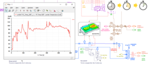
Results from a temperature probe connected to one of the IGBTs of the BCI-ROM FMU displayed in Simcenter Amesim
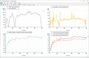
Simcenter Amesim plots showing vehicle and inverter performance
Subsequent work may include testing different inverter designs, replacing IGBTs with MOSFETs, and more, to identify which components have a critical impact on the overall system.
Bidirectional coupling
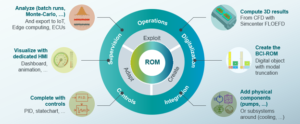
1D system-level and 3D assembly-level designs typically differ in purpose, power requirements, and simulation time. Extending 1D systems with accurate yet fast-processing 3D models enables engineering teams to create more realistic simulations at earlier design stages, ultimately helping reduce time to market. There are several benefits to using ultra-fast Simcenter FLOEFD BCI-ROMs within Simcenter Amesim:
Key user benefits of the ROM (Reduced Order Model) approach
Source: Siemens
SDE Digital Technology Co., Ltd. (SDE TECH) was established in 2014. In 2018, we were honored to become a Smart Expert Partner — a leading partner of Siemens Digital Industries Software in the Southeast Asia – Asia Pacific region for Siemens NX (Unigraphics NX), Simcenter, Solid Edge, Tecnomatix, and the Teamcenter management solution.