Tiếng Việt
 日本語
日本語 한국어
한국어
In the high-tech plastic injection molding industry, controlling surface quality is one of the biggest challenges for mold engineers and machine operators. One of the most common defects that significantly affects both aesthetics and structural integrity is the sink mark. In this article, SDE Tech provides a detailed analysis of sink mark defects, from core physical causes to practical solutions and the application of simulation technology to optimize production.
1. What is a sink mark? Identification and differentiation
To effectively eliminate any manufacturing defect, the first and most important step is to correctly define and accurately identify the nature of the issue.
1.1. Definition of sink marks on plastic products
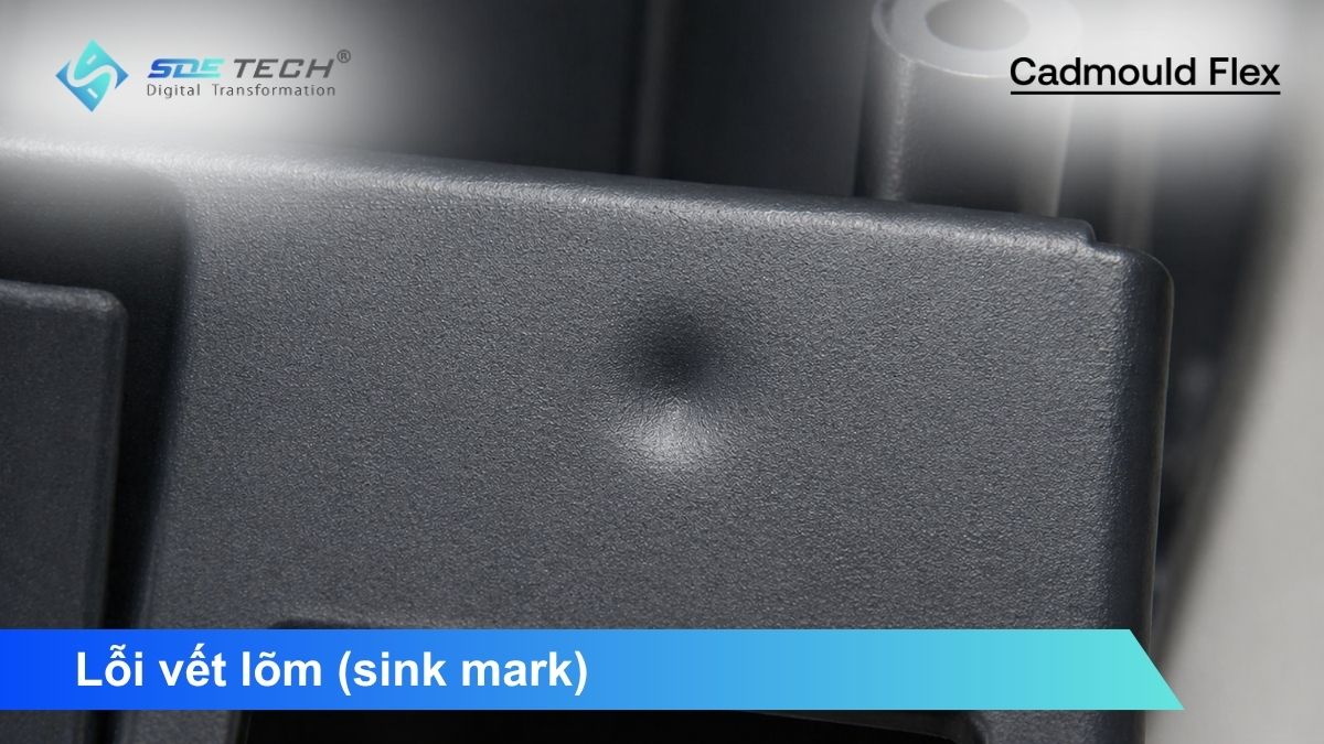
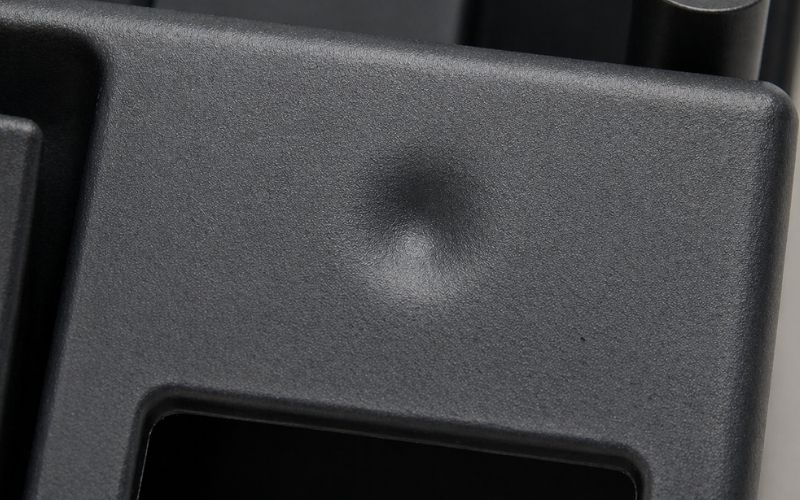
Sink marks are surface depressions that appear as unwanted indentations on plastic parts. Physically, this phenomenon occurs due to uneven shrinkage of plastic material during cooling. When the outer layer solidifies while the inner core (which remains hotter and thicker) continues to shrink, it pulls the solidified surface inward, creating visible depressions.
1.2. Practical signs of sink marks on the shop floor
In production, sink marks typically appear in areas with sudden thickness variations. They are commonly found opposite ribs, partitions, or thick material sections. Unlike mechanical scratches, sink marks usually have smooth surfaces but distort light reflection, causing significant aesthetic defects in visible parts.
2. Four main causes of sink marks
Identifying the root cause requires a multi-dimensional analysis across part design, mold design, and injection molding process parameters.
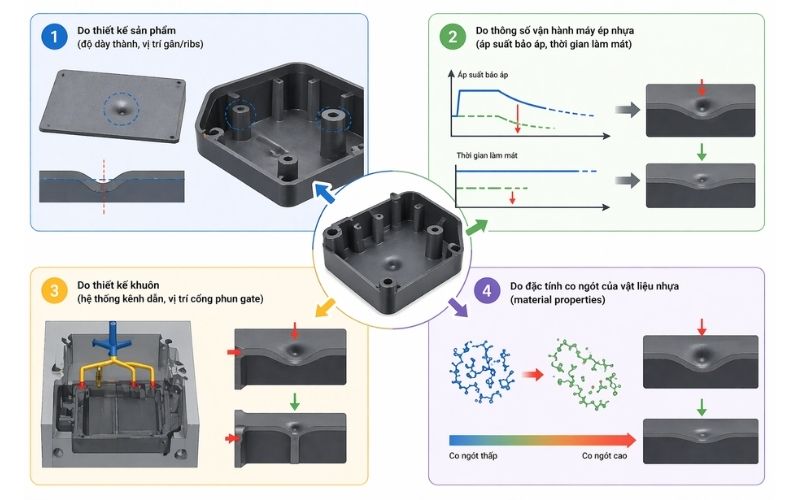
2.1. Product design issues (wall thickness, rib placement)
This is the most common cause. Excessive or uneven wall thickness creates heat accumulation zones. Especially at rib-to-wall intersections, improper thickness ratios lead to slower cooling, causing the opposite surface to sink.
2.2. Injection molding parameters (holding pressure, cooling time)
Process settings play a key role in compensating for shrinkage. If holding pressure is too low or holding time too short, insufficient material is packed into the mold. High melt temperature or short cooling time can also cause continued shrinkage after ejection, leading to sink marks.
2.3. Mold design (runner system, gate location)
Mold structure directly affects pressure transmission. A small gate or poorly positioned gate may freeze too early, preventing additional material from compensating shrinkage. Unbalanced runner systems can also cause uneven pressure distribution and localized defects.
2.4. Material shrinkage characteristics
Different materials have different shrinkage rates. Crystalline plastics such as PP, PE, and PA shrink more than amorphous plastics like ABS, PC, and PS. Changing materials without adjusting design or process parameters significantly increases the risk of sink marks.
3. Common injection molding defects associated with sink marks
In practice, defects rarely occur in isolation. Understanding their relationships helps engineers evaluate overall product quality.
- Warpage: Caused by uneven shrinkage, often occurring alongside sink marks.
- Short shot: Adjustments to fix sink marks may lead to incomplete filling.
- Weld lines & burn marks: Changes in flow or pressure may introduce additional defects.
4. Quick solutions to eliminate sink marks
When defects occur, engineers should prioritize machine parameter adjustments before modifying hardware.
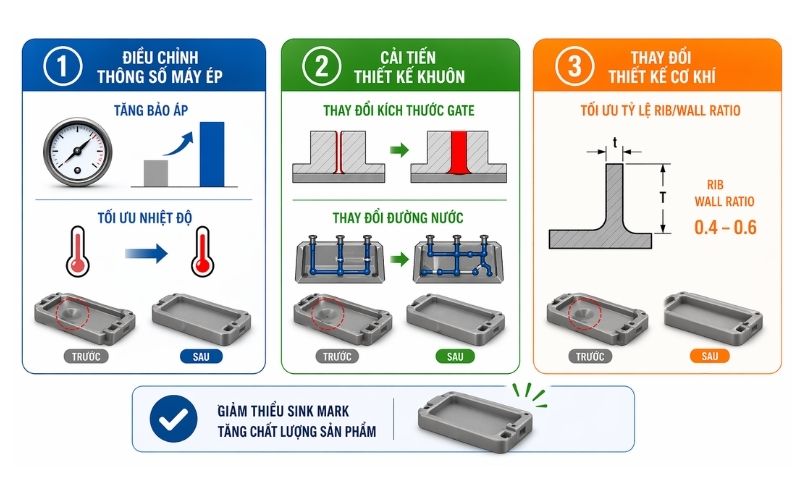
4.1. Adjust machine parameters
Increase holding pressure and extend holding time until the gate freezes. Reducing melt or mold temperature can also reduce shrinkage but must be balanced to avoid surface quality issues.
4.2. Improve mold design
Increase gate size to maintain packing pressure and optimize cooling channels to improve heat dissipation in thick areas.
4.3. Optimize part design
Maintain rib thickness at 40%–60% of the wall thickness. Reducing rib thickness is often the most effective long-term solution.
5. Using Cadmould Flex to eliminate sink marks at the design stage
Modern manufacturing uses CAE tools such as Cadmould Flex to predict and eliminate defects before mold fabrication.
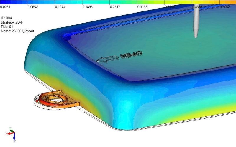
5.1. Simulation and prediction
Cadmould Flex simulates flow and heat transfer to identify high-risk areas for sink marks, allowing design optimization before production.
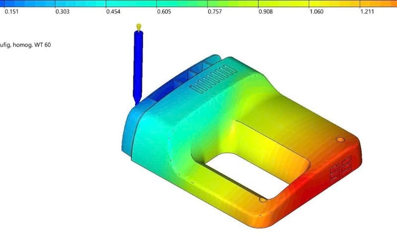
5.2. Shrinkage and cooling analysis
The software accurately calculates shrinkage and evaluates cooling efficiency, helping optimize cooling channel design.
5.3. Cost reduction with CAE
By replacing trial-and-error with simulation, businesses reduce mold trials, shorten time-to-market, and save significant costs.
6. Quick troubleshooting table
Below is a quick reference for technicians when handling surface defects:
| Issue | Cause | Solution |
| Deep sink mark | Low holding pressure, small gate | Increase pressure, check gate |
| Sink at rib base | Thick ribs | Reduce rib thickness |
| Sink with warpage | Short cooling time | Extend cooling time |
| Internal voids | Core shrinkage | Increase packing pressure |
7. FAQs about sink marks
Why doesn’t increasing holding pressure fix sink marks?
The gate may have already frozen, preventing pressure transmission into the cavity.
Do fiber-reinforced plastics reduce sink marks?
Yes, they typically have lower shrinkage but may introduce surface roughness and warpage.
How to determine optimal holding time?
Increase holding time gradually and measure part weight until it stabilizes—this indicates gate freeze time.
Sink marks are a technical challenge requiring both expertise and practical experience. Understanding material shrinkage and process parameters helps ensure product quality. In the Industry 4.0 era, using tools like Cadmould Flex from SDE Tech is key to eliminating risks early, improving efficiency, and enhancing global competitiveness.
- Website: sde.vn
- Email: sales@sde.vn
- Hotline/Zalo: 085 256 2615 – 0909 107 719