Tiếng Việt
 日本語
日本語 한국어
한국어
In precision mechanical manufacturing, the toolpath serves as a critical bridge between the design model and the final physical product. Establishing an optimized toolpath not only ensures machining accuracy but also has a direct impact on a company’s economic efficiency. This article explores the concept of toolpath and examines advanced strategies for optimizing toolpath generation in industrial manufacturing environments.
1. In-Depth Definition of Toolpath
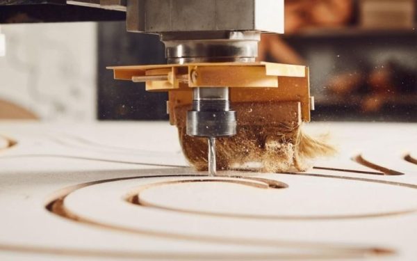
From a technical perspective, a toolpath is a structured set of coordinate data and motion control commands that define the movement of a cutting tool within a 3D space. It is the direct output of CAM software programming, used to guide CNC machines in removing material from a workpiece and forming the desired geometry.
An accurate toolpath consists of a continuous sequence of points, where each point contains coordinate values (X, Y, Z) along with auxiliary parameters such as feed rate, spindle speed, and tool vector orientation. These data are subsequently processed by a post-processor, which converts them into G-code—the machine-readable language executed by CNC controllers.
2. Key Data Components of a Toolpath
To construct a complete and effective toolpath, CAM software must integrate multiple layers of data. When analyzing what a toolpath is, it is essential to break down the following core elements:
- Position Data: The set of coordinates that define the path through which the tool center or tool tip must travel.
- Technology Parameters: Including cutting speed and feed rate, optimized based on the material and machining conditions.
- Link Moves: Transitional movements that connect different machining regions, including safe retracts and approach motions to and from the workpiece.
- Normal Vector Data: Defines the tool’s orientation relative to the surface, which is especially critical in complex surface machining and 5-axis operations.
Any omission or misconfiguration of these components can lead to critical risks such as machine collisions, tool breakage, or severe surface defects on the machined part.
3. Classification of Common Toolpath Strategies in CAM Programming
Depending on geometric characteristics and technical requirements, the most common types of toolpath strategies include:
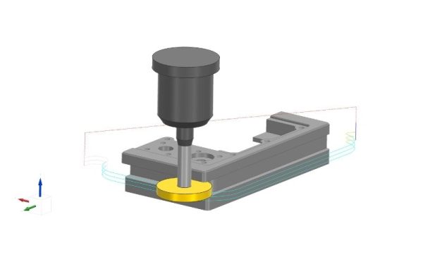
3.1 2D and 2.5D Toolpath Strategies
These strategies are typically applied to parts with planar geometries or cavities with constant depth. In this approach, the tool primarily moves within the XY plane. Common toolpath types include Pocketing, Facing, and Profiling. Although considered fundamental, optimizing toolpaths at the 2D level can still deliver significant reductions in idle time and overall machining cycle time.
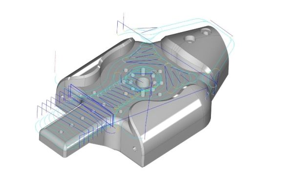
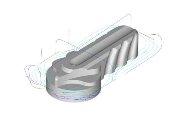
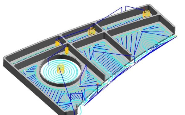
3.2 3D Toolpath Strategies (Surface Machining)
For machining complex curved surfaces or molds, CAM software generates toolpaths that either follow the surface contour or run in parallel passes. Surface quality is highly dependent on the stepover parameter (lateral tool engagement). If the stepover is too large, the surface finish becomes rough; if too small, machining time increases unnecessarily.
3.3 High-Speed Machining (HSM) Toolpath Strategies
High-Speed Machining represents a major advancement in modern manufacturing. HSM toolpaths are designed to avoid sharp directional changes, instead utilizing smooth arc transitions to maintain a consistent cutting velocity. This approach reduces mechanical shock on the spindle and helps protect cutting tools from excessive heat buildup, ultimately improving tool life and machining stability.
4. Why Toolpath Optimization Is Critical for Manufacturing Efficiency
Toolpath optimization is not simply about making machines run faster—it is a comprehensive strategy to enhance overall equipment effectiveness (OEE) and maximize CNC machining performance.
- Reduced Tool Load: A well-designed toolpath maintains consistent chip thickness, minimizing heat buildup and significantly extending tool life.
- Improved Surface Quality: Optimizing lead-in and lead-out strategies helps reduce tool marks and minimizes the need for secondary finishing operations.
- CNC Machine Protection: Smooth and continuous toolpaths reduce vibration, thereby limiting wear on the spindle and ball screw system.
- Shorter Cycle Time: Optimizing non-cutting movements (rapid moves) can reduce machining time by 15–30% per part, leading to substantial productivity gains.
5. Technical Factors Affecting Toolpath Quality
To ensure that a toolpath design operates effectively on actual CNC machines, several critical technical factors must be considered:
- Chordal Deviation (Tolerance Setting): This refers to the deviation between the theoretical curve and the linear segments executed by the CNC machine. A smaller tolerance results in smoother toolpaths but significantly increases G-code file size.
- Controller Capability (Look-Ahead Function): Modern CNC controllers can read hundreds of lines of code in advance to optimize speed through corners. If the toolpath is overly complex and exceeds the controller’s processing capability, it may cause machine “stuttering” or inconsistent motion.
- Chip Control Strategy: An effective toolpath must ensure efficient chip evacuation to prevent chip recutting, which can lead to poor surface finish or tool breakage.
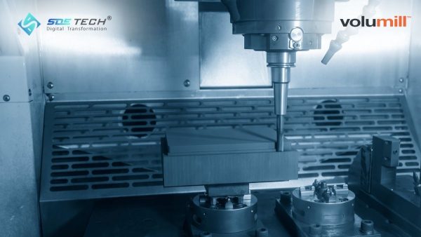
SDE TECH delivers world-class software solutions such as Siemens NX and Mastercam, integrated with advanced toolpath computation technologies. For example, innovations like VoluMill and FeedControl enable ultra-efficient roughing by maintaining a constant tool engagement angle, resulting in faster material removal while preserving tool life and machining stability.
6. Frequently Asked Questions (FAQ) on Toolpaths
6.1 What is the difference between a Toolpath and G-code?
A toolpath essentially represents geometric and technological data calculated within the CAM environment (typically in the form of CL-data). In contrast, G-code is the machine-specific programming language generated from the toolpath via a post-processor, enabling CNC machines to interpret and execute the instructions.
6.2 Why do CNC machines stutter when running complex 3D toolpaths?
This issue is typically caused by an excessively dense distribution of coordinate points that exceeds the controller’s buffer capacity, or by overly tight tolerance settings. To resolve this, it is necessary to optimize the smoothing/filtering parameters within the CAM software.
6.3 How can machining time be reduced without compromising tool life?
It is recommended to apply High-Speed Machining (HSM) or trochoidal milling strategies. These approaches maximize the effective cutting length while maintaining low tool load, allowing higher cutting speeds without sacrificing tool integrity.
Understanding what a toolpath is and how it functions is fundamental to enhancing the manufacturing capabilities of any precision engineering enterprise. Investing in high-quality CAM software and advanced toolpath optimization processes is ultimately an investment in machine longevity and superior product quality.
At SDE TECH, our team of experts is ready to support your business with consulting and technology transfer for advanced CNC programming solutions. Contact us today to unlock your full production optimization potential.
- Email: sales@sde.vn
- Hotline/Zalo: 085 256 2615 – 0909 107 719