Tiếng Việt
 日本語
日本語 한국어
한국어
In 2008, Barack Obama was elected President. That year also saw the global stock market crash and the first appearance of a digital currency called Bitcoin. At that time, I had just graduated with a Master’s degree from Clemson. 2008 was also the year the first version of 3D CAD (the CAD environment integrated into Simcenter STAR-CCM+) was released. The idea was to bring CAD preparation for CFD simulation into a fully integrated CFD software environment. Much has changed since 2008!
Previously, 3D CAD was fairly basic. It was a powerful tool with a few separate operations to handle a few hundred parts. However, it still worked with existing capabilities and aimed for greater things. Now, it provides an integrated CAD environment allowing CFD engineers to do everything necessary to prepare geometry and parameterize large CAD models.
You don’t have to go back over a decade to see the innovation speed in Simcenter STAR-CCM+. Seven months ago, we released two new versions of Simcenter STAR-CCM+ with a range of new features in 3D CAD modeling—all aimed at making a CFD engineer’s work in the CAD world easier!
Watch here: https://www.youtube.com/watch?v=5tE_0p1b030
Creating CAD within CFD Software
If you don’t believe me, check the dishwasher in the video below. My colleague, David Mann, modeled it entirely using 3D CAD, as described in his recent blog Unlocking the Potential of Hybrid Multiphase CFD Simulation.
David didn’t just prepare CAD for CFD; he created the entire geometry from start to finish entirely within the CFD simulation software. Then, using Adaptive Mesh Refinement (AMR), he visualized multiphase CFD behavior inside the dishwasher (click the video to see more). This is a clear illustration of the power of the integrated environment.
Multiphase CFD visualizing dishwasher operation using AMR
Such a model would not have been feasible in 2008 when this tool was first launched. Today, 3D CAD provides all necessary tools to efficiently set up large CAD models, prepare geometry, or parameterize these geometries for simulation.
Preparing Complex CAD Models for CFD Simulation
While most people—even my 5-year-old son—can see a cool sports car when it’s assembled, simulation engineers see over 15,000 parts to model in a single workday. Fortunately, Simcenter STAR-CCM+ provides tools to accelerate this workflow.
Easily Import Large CAD Assemblies
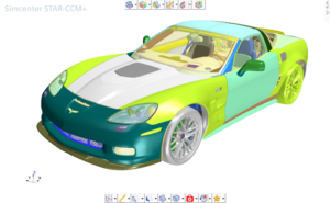
With Simcenter STAR-CCM+ 2021.2, users can directly import 10,000 CAD models, such as the Corvette shown below, into 3D CAD. (Notice the new icon toolbar that wasn’t there before.) Previously, this model would import into ‘Parts’ instead of the 3D CAD environment. Now, it can be imported directly into 3D CAD to arrange and reduce data size before meshing.
Importing the full Corvette CAD model into 3D CAD
Setting Up Complex CAD Models for Simulation
The latest release allows more than importing large CAD models; you can now interact with the model in real-time. Over the past four cycles, we focused on improving display performance to handle 10,000-part CAD models in 3D CAD. Tools like ‘section cut’ and ‘explode view’ allow you to examine the model while working, making CAD preparation smoother for CFD simulation.
3D CAD Section view to review the model
Additionally, search, tagging, and design filters allow you to structure data into efficient tree hierarchies, add tags, or remove unwanted parts.
Looking at the Corvette again, after setting up the model with tags and body groups, the original 8,000 body groups and 15,000 bodies were reduced to about 10 body groups and 15,000 bodies, making it easy to tag and automate meshing. The image below shows the reorganized hierarchy for the Corvette model.
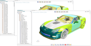
Setting up complex CAD models for CFD
Geometry Preparation
When importing large CAD models, common issues include gaps and intersections between parts, CAD translation problems, duplicate parts, missing faces, and model errors. Performing VTM analysis on the Corvette model generates fluid and solid volumes using surface wrapping technology.
Surface wrapping creates a watertight volume without leaks into the main cabin, handles geometry issues (gaps, intersections), and captures original geometric features. Missing faces and model errors can be identified with search tools and fixed in 3D CAD using delete, boolean, repair, defeature, and fill operations.
3D CAD geometry preparation – Unified operations
Before 2021.2, these operations were time-consuming. With the introduction of incremental surface creation (avoiding tessellating the entire assembly whenever a geometry operation is applied to a few bodies), performance is significantly improved.
Accelerating CAD Preparation with an Intelligent UI
The recent release introduced an icon toolbar organizing all features to reduce unnecessary clicks when searching through the right-click menu.
‘Recent actions’ and ‘Favorite features’ are my favorites in this new toolbar, as seen in the Corvette image above. ‘Recent actions’ lets you quickly access features used recently, while ‘Favorite features’ allows you to list frequently used operations. Both help users access features faster without digging through long option menus.
Conclusion
By 2021, 3D CAD had changed significantly from its initial release. Since 2008, we’ve continuously enhanced CAD preparation to be stronger, faster, easier, and more automated for CFD simulation. Cleaning up geometry is like washing dishes—once you see the beauty of a fully integrated automated workflow, you’ll never want to return to a disconnected manual process.
Source: Siemens
SDE TECHNOLOGY CO., LTD (SDE TECH) was established in 2014. By 2018, we became a Smart Expert Partner – a leading partner of Siemens Digital Industries Software in the Southeast Asia – Pacific region for Siemens NX (Unigraphics NX), Simcenter, Solid Edge, Tecnomatix, and Teamcenter solutions.

For businesses and customers who wish to contact SDE TECH, please use the following information:
E-mail: sales@sde.vn – tech@sde.vn
Hotline: 0909 107 719
Website: www.sde.vn