Tiếng Việt
 日本語
日本語 한국어
한국어
DIGITAL TWIN SIMULATION: CREATE EFFICIENT FEA WORKFLOWS WITH SIMCENTER
This is the third article in a series by David Haag from Haag Enterprises, an advanced digital engineering firm providing product development, industrial equipment, and automation services.
Part 1 of this series shared approaches to creating efficient workflows using Simcenter Femap, essentially a high-level overview of finite element modeling workflows. In this post, we will dive into more specific topics to help set up increasingly complex models.
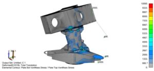
The solver has completed, and it’s time to review the results. However, with larger models, this becomes challenging due to the number of entities on screen. For example, Figure 1 below shows the full model, considering only bolt connections and/or contact stresses at welds, which is difficult to interpret due to the visibility obstruction caused by flange plates.
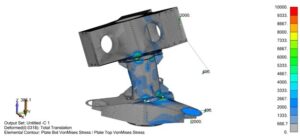
Figure 1. Full model displayed (all three welds) in a deformed state with Von Mises stress contours
Groups
You may be familiar with Layers; however, it has some limitations, so we introduce the Groups feature.
The Groups command allows you to organize the model by geometry or FEM entities that can be recalled later. Think of it as visual display states that you can save for later use. Groups can be viewed individually, with boolean operations, or all at once. Note that an entity can belong to multiple groups, unlike layers.
Groups can be created automatically by type (e.g., material, property, solid, surface, element, etc.). Once a group is created, you can manually add items to it or enable “Automatic Add” so that anything created afterward becomes part of that group.
Figure 2 shows the Middle Weldment group created using Solids. You can activate this group by double-clicking it, then use Display Only by right-clicking the group and selecting Show Active Group.
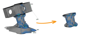
Figure 2. Create Middle Weldment group using Group -> Operations -> Generate Solids. Then separate it by right-clicking the group name in the model tree and selecting Show Active Group
Draw/Erase Toolbar
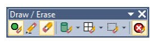
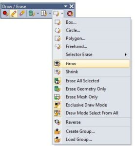
This toolbar provides an alternative method to select entities to temporarily display or hide them. Entities can be selected using any combination of commands by selecting geometry, mesh, and/or regions. Draw mode displays entities added to the list, while Erase mode simply hides them.
We can isolate the middle weldment using this tool, but once erased, that display state is lost. However, there is an option to create a group from the current display state.
Slicing/Sectioning with Clipping Plane
Clipping Plane allows you to select or create a moving plane used to cut the model. The plane can be toggled on and off. For CAD users, this is a standard way to inspect parts and assemblies, but it lacks the advanced functionality of Groups and Draw/Erase commands.

Figure 3. Full model with clipping plane
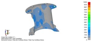
Figure 4. Middle Weldment group in Display Only mode with clipping plane
Grow/Shrink
This is an option in the Draw/Erase toolbar that allows selecting an element or regions of elements and expanding the display of neighboring elements by choosing Grow, or reducing it by choosing Shrink.
A next action could be to save the screen as a Group, which can be quickly recalled later. For example, if this is an area of interest, we can save it into a group, re-run analysis with different parameters, or use a different solver while maintaining the same entity visibility for comparison results.
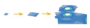
Figure 5. Starting with a single element, we can use the Grow option in the Draw/Erase toolbar to expand the number of displayed elements.
Deformed Model Visualization
In post-processing, we can display the undeformed and deformed models. Additionally, for the undeformed state, we can view the actual deformations or scale them as a percentage. The benefit is seeing how the material behaves, helping determine next steps, which may include mesh refinement, adjusting plate thickness, adding stiffeners, etc.
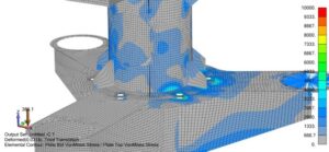
Figure 6. Deformed model – actual displacements shown
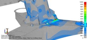
Figure 7. Deformed model – scaled displacements at 5%
Summary
The Group and Draw/Erase commands in Simcenter Femap help quickly set up increasingly complex models, allowing more time to produce accurate digital twins. They can be used independently or together, as demonstrated in the video below.
Source: Siemens
Công ty TNHH Công Nghệ Số SDE (SDE TECH) was founded in 2014. In 2018, we were honored to become a Smart Expert Partner – a leading partner of Siemens Digital Industries Software in the Southeast Asia – Pacific region for Siemens NX (Unigraphics NX), Simcenter, Solid Edge, Tecnomatix, and Teamcenter solutions.
Businesses and customers can contact SDE TECH as follows:
E-mail: sales@sde.vn – tech@sde.vn
Hotline: 0909107719
Website: www.sde.vn