Tiếng Việt
 日本語
日本語 한국어
한국어
Vapor chambers are increasingly becoming a popular thermal solution for electronic devices. They can be found in a wide range of systems, from mobile phones to high-power laptops and gaming consoles. In this blog, we will explore exactly what a vapor chamber is; learn how to model a vapor chamber using Simcenter Flotherm XT; and analyze the thermal benefits of vapor chambers compared to traditional heat sinks.
What is a Vapor Chamber?
A typical vapor chamber consists of a hollow copper enclosure (chamber) filled with a small amount of liquid water. This chamber is then vacuum-sealed under atmospheric pressure, allowing the liquid water to evaporate (vaporize) at temperatures below 100°C.
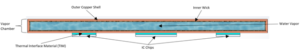
Typical structure of a vapor chamber
The operating principle behind a vapor chamber is similar to a typical heat pipe. It relies on the evaporation and condensation cycle of water to transfer heat from the hot section to the cold section. Then, an internal wick acts as a carrier, returning condensed liquid water back toward the evaporating section through capillary action. The cycle can then begin again.
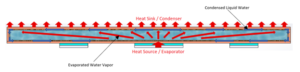
Vapor chamber operating cycle
Vapor chambers can be used as a thermal solution to spread and dissipate heat passively. This is often seen in some mobile phones where space is limited. However, vapor chambers can also be mounted onto the base of conventional heat sinks when higher cooling performance is required.
Are Vapor Chambers Better Than Heat Pipes?
Although the operating cycle of both vapor chambers and heat pipes is similar, the choice of thermal solution depends on the application. For example, vapor chambers are very effective at spreading heat evenly across a horizontal surface, whereas heat pipes excel at transferring heat from one location to another.
Vapor chamber vs. heat pipe
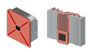
The flat shape of a vapor chamber allows better surface contact with the IC chip or the base of a heat sink, creating a more direct thermal path. This contrasts with the cylindrical shape of a heat pipe, which cannot be mounted directly onto a component. Instead, additional or modified connectors are required before heat can reach the pipes.
Modern manufacturing can produce vapor chambers as thin as 2.5mm. This is particularly useful in compact electronics such as mobile phones or laptops with vapor chambers. Additionally, the thin design makes vapor chambers less orientation-sensitive, unlike traditional heat pipes where gravity can affect cooling performance.
To visualize the thermal benefits of a vapor chamber, some CFD analysis can be performed using Simcenter Flotherm XT.
Modeling a Vapor Chamber
Let’s start by taking a typical model of a high-power gaming console. Most of the heat dissipation comes from the System on Chip (SoC) generating 100 watts of heat. We will compare the SoC temperature with two different heat sinks: first, a basic standard copper base heat sink, then a heat sink with a vapor chamber base. Both will be the same size and equipped with aluminum fins.
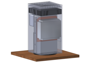
Model used to compare heat sinks
Modeling a vapor chamber explicitly is not a simple effort. It requires significant computation time (and engineer effort) to model the evaporation and condensation cycles that they operate on. Therefore, creating a simplified model is often quicker and more convenient, approximating the characteristics of the desired vapor chamber.
We will take the standard heat sink from the model above and modify the copper base into a sandwich base with solid conduction layers representing the vapor chamber:
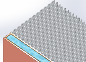
Cross-sectional image simulating solid material layers used in the vapor chamber, mounted on aluminum fins
Now we can apply the effective thermal conductivity of the wick and vapor layers we added. We will use values that approximate the vapor chamber in its operating state:
Wick = 40 W/(m·K)
Vapor = 30,000 W/(m·K)
You can notice the very high effective thermal conductivity of the vapor. This provides insight into the cooling performance we can expect from a vapor chamber.
CFD Analysis
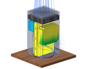
The first analysis model uses the standard copper base heat sink. The second solution analyzes the vapor chamber heat sink. Forced airflow through the device can be seen below:
By creating a temperature plane chart along the vertical axis, we can examine the SoC temperature when using the basic copper base heat sink:
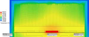
Standard copper base heat sink
The SoC reaches a temperature of 89°C, with heat accumulation concentrated around the center of the heat sink. Notice that ΔT of 10°C occurs from the center to the outer edge of the copper base. This shows that heat cannot efficiently reach the outer aluminum fins, making the use of surrounding air between the fins less effective.
Now let’s consider the SoC temperature when using a vapor chamber heat sink:
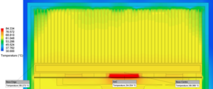
Vapor chamber heat sink
This plane chart shows the SoC temperature drops by 5°C compared to the copper base heat sink, which is a great improvement! Additionally, the vapor chamber exhibits a ΔT of only 3°C from the center to the outer edge. This demonstrates more uniform lateral spreading of the SoC heat—a common benefit of using vapor chambers.
As a result of improved lateral heat spreading, the vapor chamber allows heat to be transferred more evenly through the upper sections of the aluminum fins. This enables better utilization of the total airflow across all fins, unlike the copper base heat sink which only effectively cools the center fins and central airflow.
Conclusion
Modern electronic devices demand more advanced thermal technologies than ever, and vapor chambers can be an excellent thermal solution. Using Simcenter Flotherm XT, we visually demonstrated the thermal benefits of vapor chambers, showing how they can provide improved cooling performance with better heat dissipation compared to traditional heat sinks of the same size.
Source: Siemens
SDE Digital Technology Co., Ltd. (SDE TECH) was established in 2014. By 2018, we were honored to become a Smart Expert Partner – a leading partner of Siemens Digital Industries Software in the Southeast Asia – Pacific region for Siemens NX (Unigraphics NX), Simcenter, Solid Edge, Tecnomatix, and Teamcenter solutions. Businesses and customers can contact SDE TECH as follows: